Timer
During the construction of a rocket with the club SpaceCampus of the University of Bordeaux, I had to design and assemble a small circuit handling the opening of the parachute hatch, my first PCB.
The purpose of this circuit is to deploy the parachute at the right time, that is, when the rocket reaches the apogee. To do this, I chose to use a small microcontroller called PIC12F683. It detects when the rocket takes off thanks to a cable attached to the launch pad which disconnects from the PCB at launch. Then, the chip starts a countdown of 5.3 seconds before commanding the opening of the parachute hatch. This duration of 5.3 seconds was calculated using a simulation (Stabtraj).
This is what the PCB looks like when printed and when all the components are soldered:
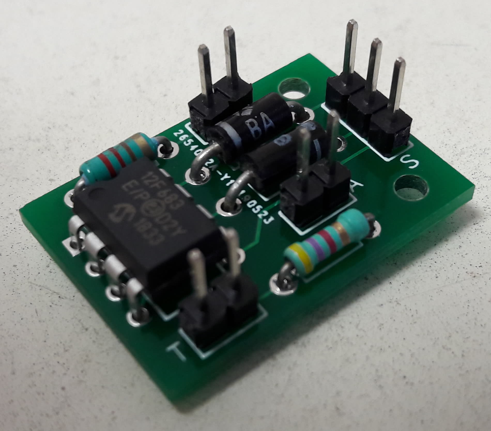
You will have noticed several connectors. As you can see in the diagram below, each one is labeled with a letter:

Here is the signification of the letters:
L— LED: The light indicator giving the program status is connected here.A— Power supply (Alimentation in French): The 5V power supply is connected here.S— Servomotor: The servomotor used as a latch for the parachute hatch is connected here.T— Trigger: The socket for the trigger cable is connected here.
Finally, during the launch, the timer worked wonderfully and the parachute deployed on time, allowing a smooth and damage-free landing.